Open-source micro drone · G1 and G2 approved · Gate G3 PCB layout draft
MicroScout design explorer
A 95 mm, 2S brushless ESP32-S3 quadcopter designed to be quick, to flip and to survive crashes: a one-piece ducted nylon frame is meant to protect soft-mounted electronics, and a Python SDK flies it - in a simulator today, on the drone later. This page shows the Gate G1 rev B draft and lets you change the assumptions.
Overview
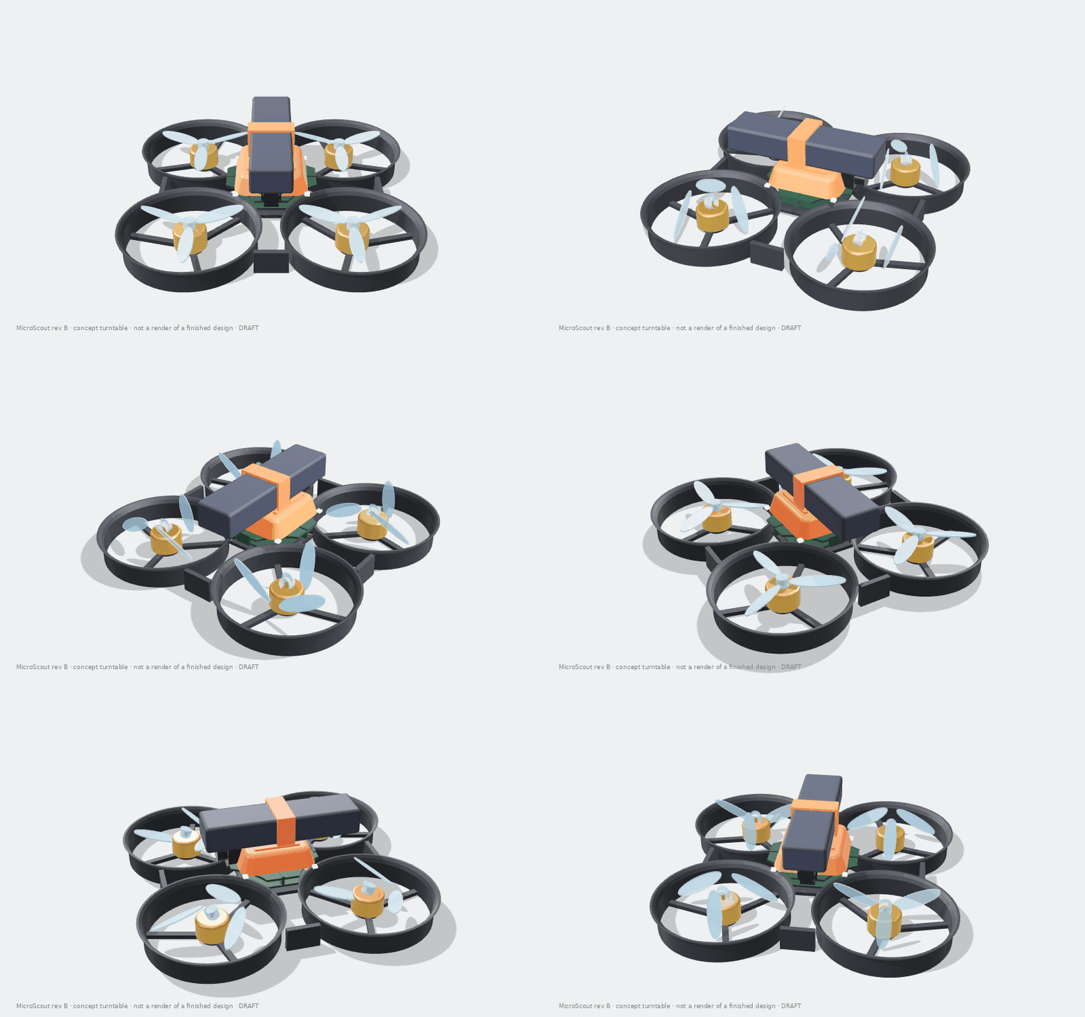
3D concept
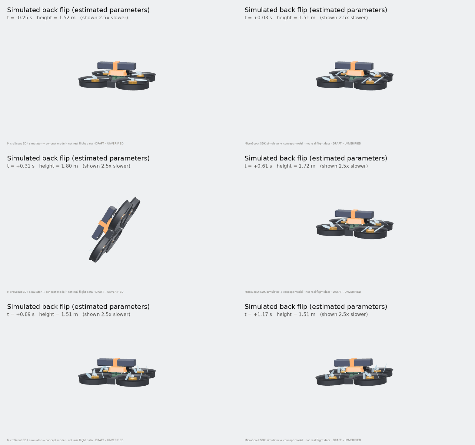
Drag to orbit, scroll or pinch to zoom. The frame and canopy are parametric CAD; motors, props, battery, boards and sensors are simplified envelopes. The flights are replayed from the SDK simulator with estimated parameters - not real flight data.
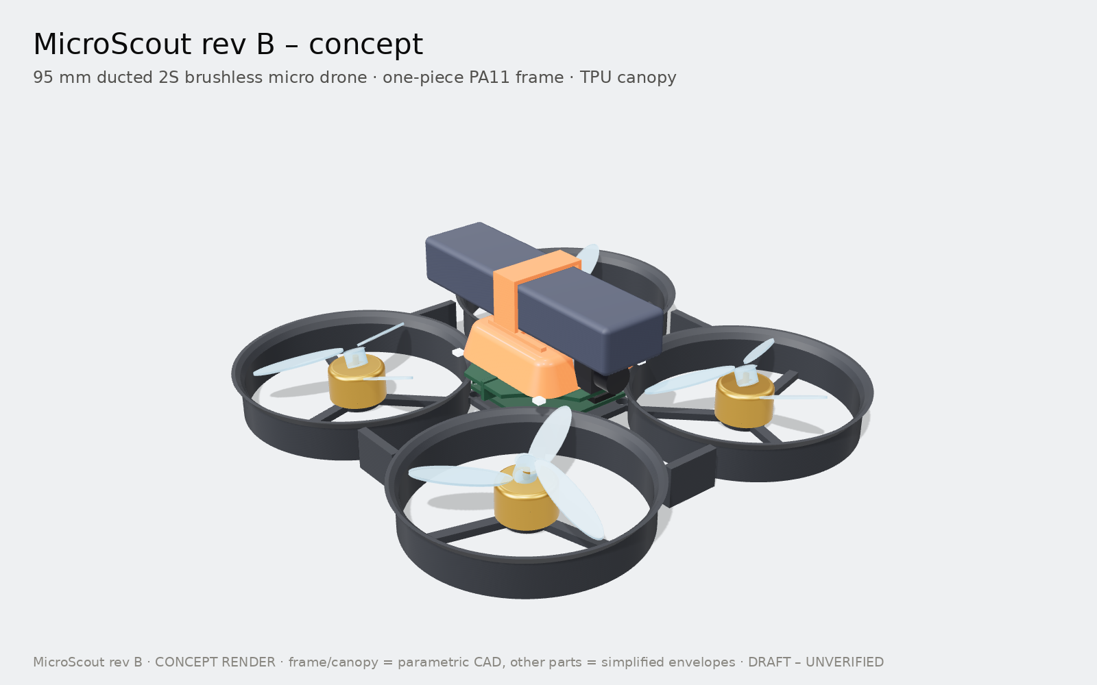
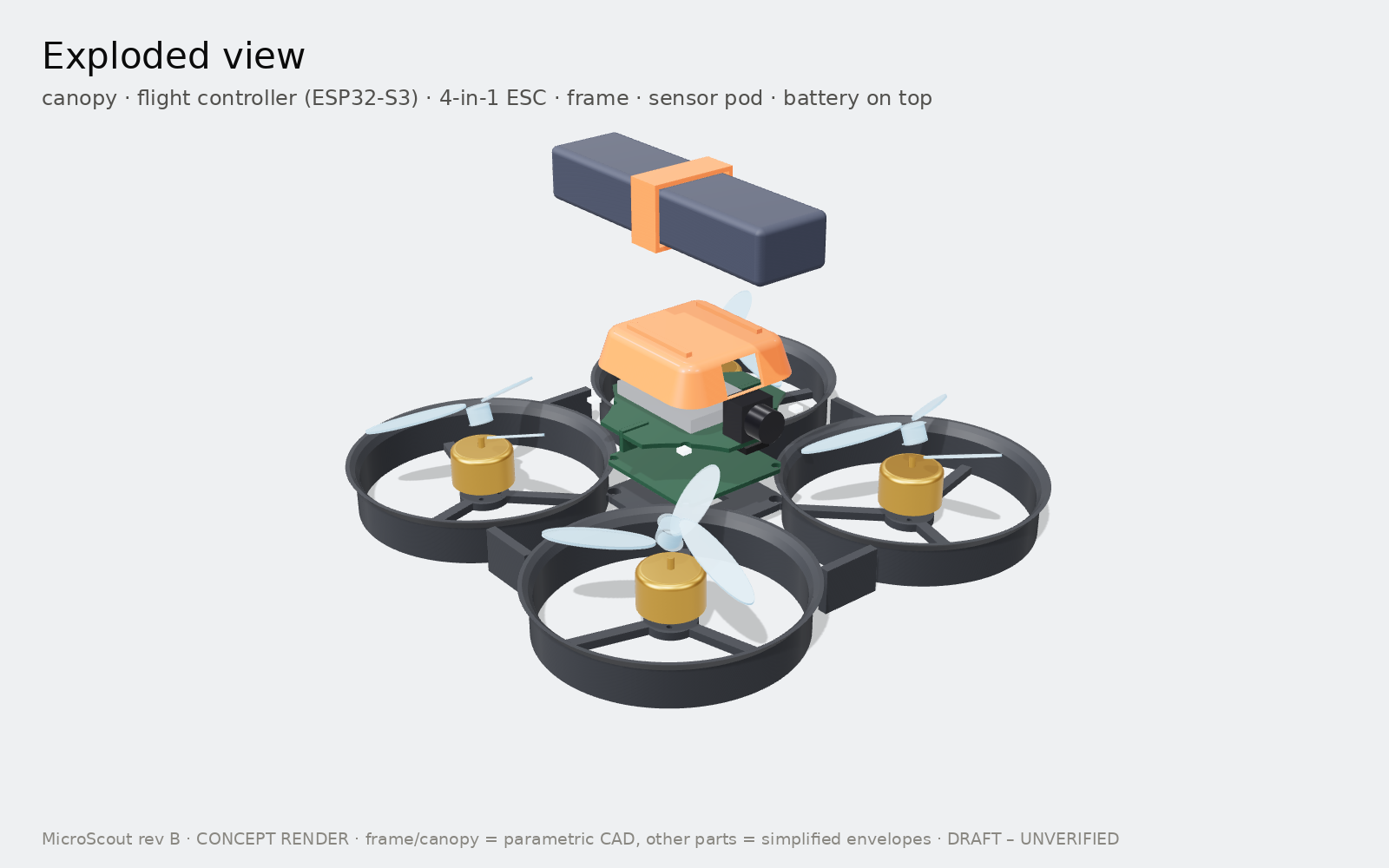
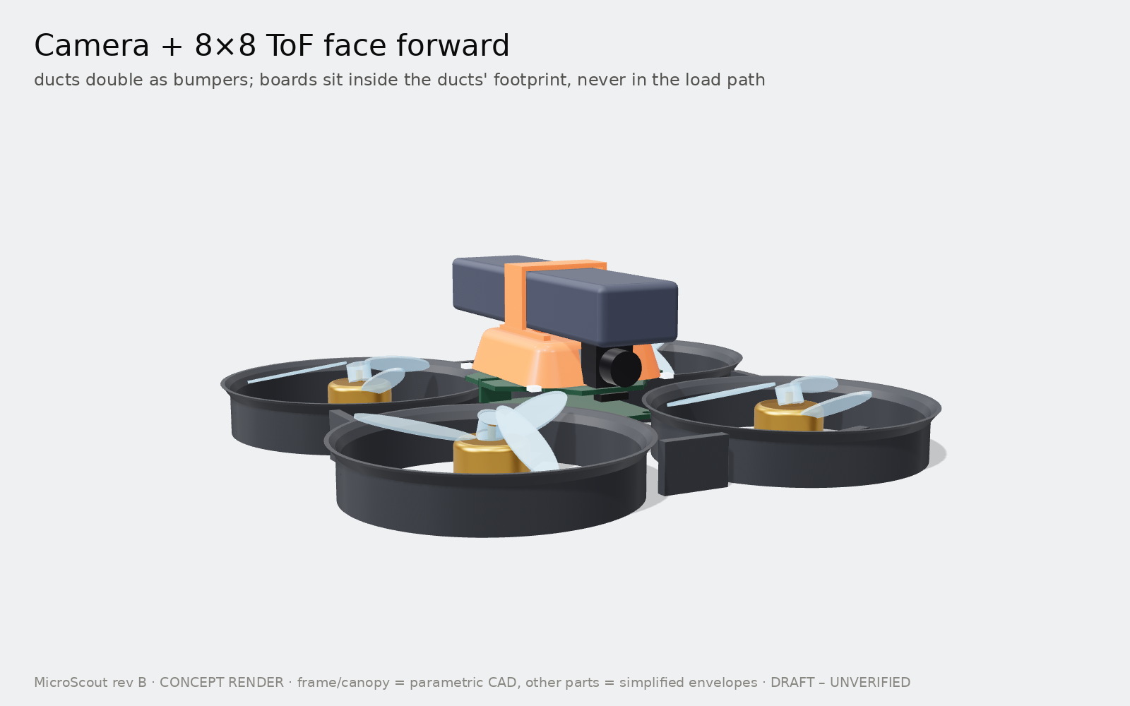
Fly it, or program it
As a pilot
Any ExpressLRS radio, or a phone on the drone's Wi-Fi (app planned for M8).
| Mode | Sticks mean | It helps by |
|---|---|---|
| Beginner | speed | holding height and position, stopping before walls |
| Sport | tilt angle | levelling itself, holding height |
| Acro | rotation rate (1000 °/s) | staying out of your way - flips, rolls |
One-button flips in any mode above 1 m. Kill switch, link-loss landing, low-battery landing and a 3 m ceiling are built in. Flying guide →
As a programmer
pip install -e software/microscout_sdk
import microscout
with microscout.connect("sim") as drone:
    drone.takeoff(1.0)
    drone.move(forward=1.0)
    drone.flip("back")
    drone.land()
Same API for the simulator now and the drone later. Drop down to rates, attitude or velocity setpoints and run your own PID, LQR or MPC at 100 Hz. Programming guide →
Or try it right here: the Flight Lab
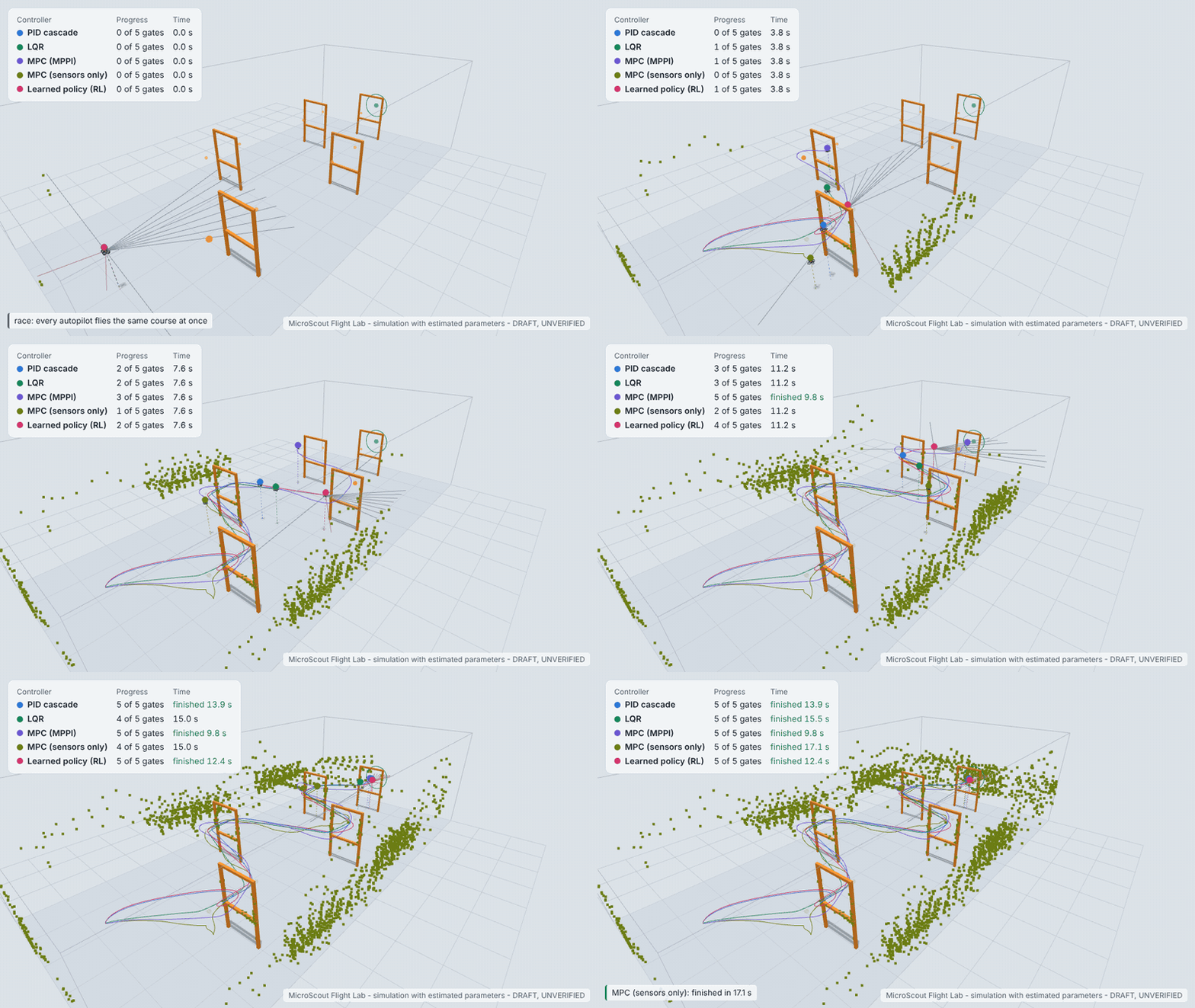
Fly MicroScout yourself in your browser (keyboard, gamepad or touch), race five autopilots through obstacle courses (or one you build), and train it with reinforcement learning while you watch. Simulation with estimated parameters. Open the Flight Lab · How it works
What-if calculator
The same hover model as budgets.py. Start values are the current estimates (G1 model, updated at G2); move them to see how much margin each assumption buys. Hover time = capacity × HV derate × usable fraction ÷ (motor current + electronics current).
Weight budget
Table view
Schematics (approved at G2)
Generated from Python (tools/sch) as KiCad 7 files: flight controller (4 sheets), 4-in-1 ESC (5 sheets) and the ToF satellite boards. The agent's checks report 0 errors and KiCad netlists identical to the source; KiCad's own ERC and a human review are still to come. Click a sheet for the full PDF.
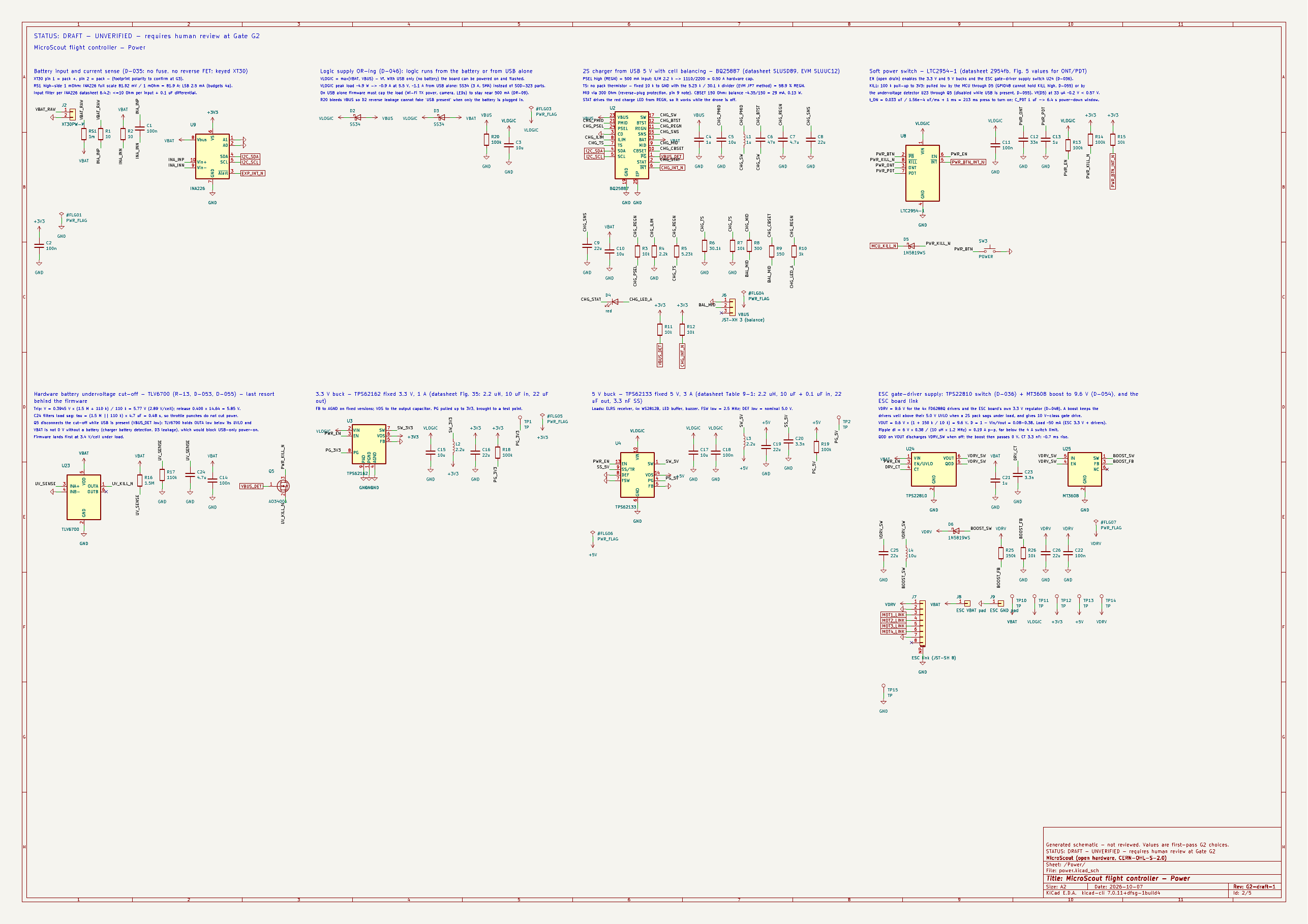
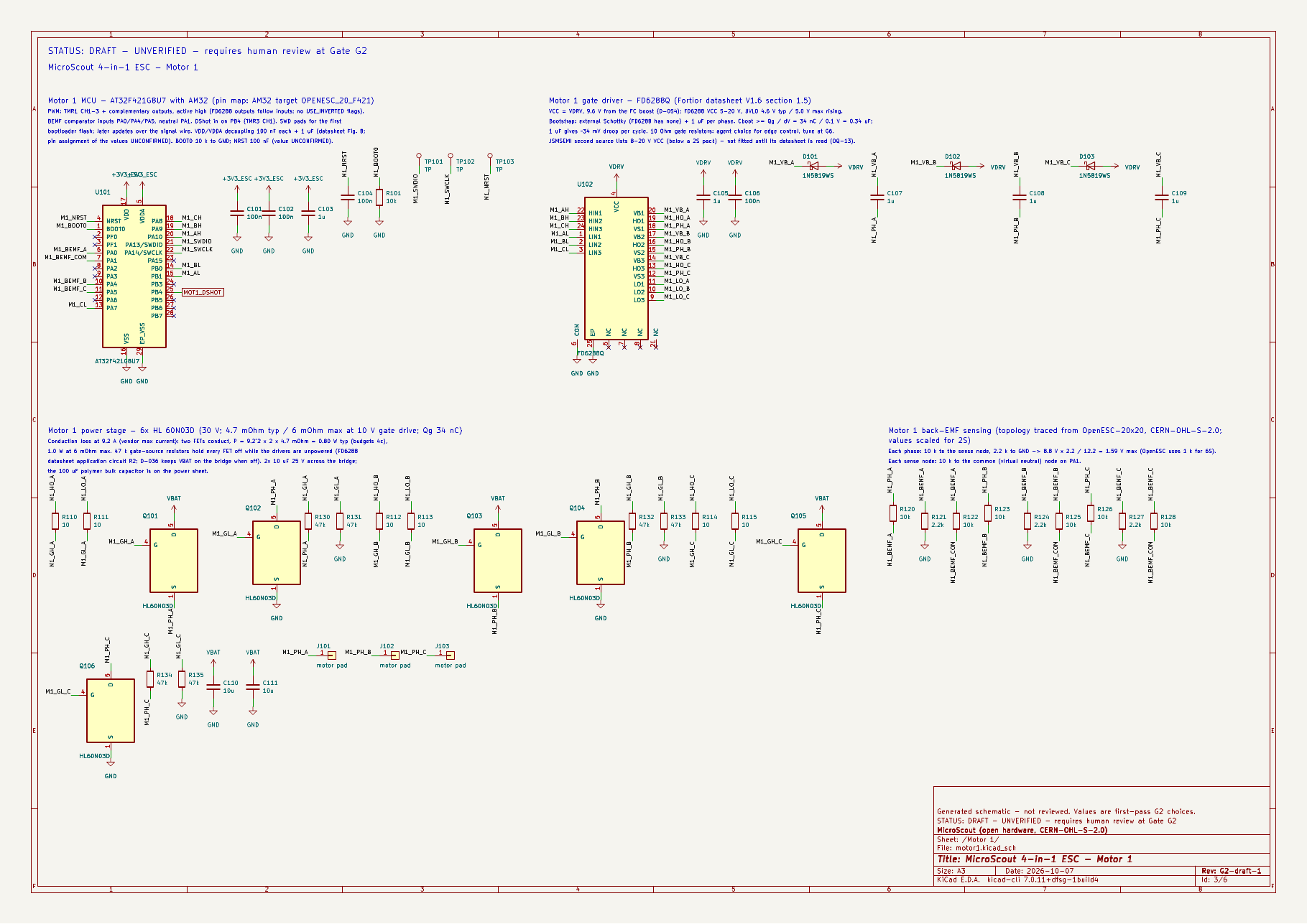
G2 review package → reference-design comparison, protection summary, pull-ups and strapping, costed BOM. G3 PCB layout package → layer plots, 3D renders, DRC and open connections.
ESP32-S3 pin map
35 of the 36 GPIOs on the ESP32-S3-WROOM-1-N8R2 module are used; GPIO1 is spare. Hover or tab through the pins for details; the chips filter by function. Pin order follows the module (1–14 left, 15–26 bottom, 27–40 right); the drawing is not to scale.
Pick a pin
Strapping pins (◆) decide how the chip boots, so the circuits on them were chosen to give the right level at reset.
Table view of all pins
Power and cost
Electronics current, 3.3 V rail
Priced parts per drone
Table view
How it boots
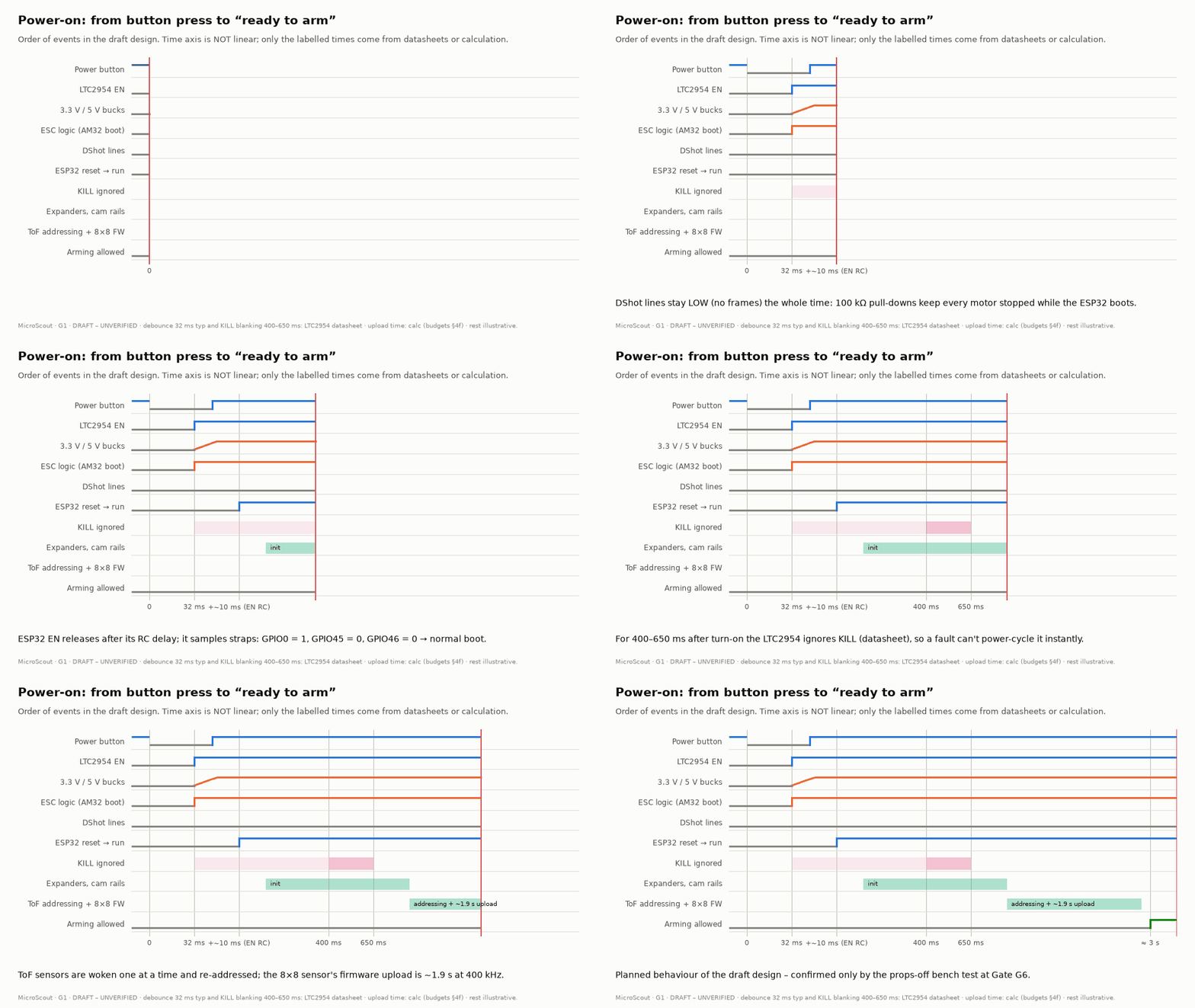
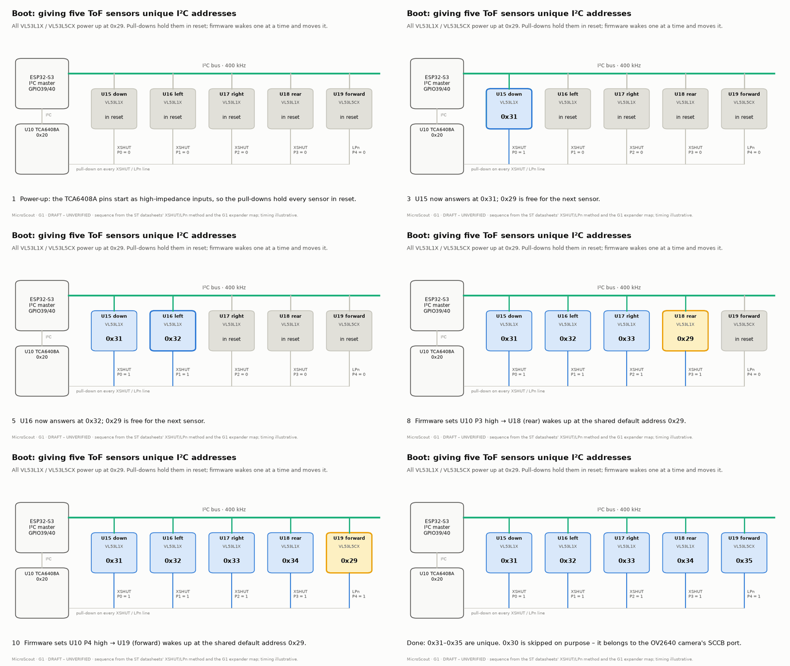
Two short animations of the planned start-up behaviour. They illustrate the draft design; the real behaviour is checked on the bench, props off, at Gate G6.
Figures
Generated by tools/viz/figures.py from the same data as this page, in light and dark versions.
Open questions at Gate G3
Decisions the owner makes before the schematic starts. The recommendation is the drafting agent's.